Pressure control valves are widely used in every hydraulic system to keep the
system safe and offers multiple functions to maintain equipment smoothly. Three
types of Pressure control valves is usually used to the
hydraulic system.
A) Pressure relief valve
B) Pressure reducing valves
C) Flow control valves
Pressure control directional valves
Suppose your system maximum pressure capacity is 180 kg and you need only 80 kg as working pressure. To do that, first you need to set the pressure relief valve at 80 kg. When pump starts to create flow and when it will reach at 80 kg then your system will be developed by 80 kg working pressure and it is developed continually when it exceeds 80 kg pressure then relief valve opened and excessive pressurized flow go to hydraulic tank. There we have different types of pressure relief valve is listed below:
As an example, your actuator is working after every five minutes in each time. Now you want to keep your pump and prime mover in unloading condition in break time then you can use solenoid operated pressure relief valve.types of Pressure control valves
A) Pressure relief valve
B) Pressure reducing valves
C) Flow control valves

|
|
Fig: Pressure relief valve |
A) Pressure relief valve
Pressure relief valve is a pressure control directional valve. Usually Pressure relief valve used to hydraulic system to control the fluid pressure as needed. Relief valve can be set in different pressure value for the system as per its requirement. As an example, if you need 80kg pressure for the system then you can set it by adjusting the screw or if you need more pressure then it is possible. The higher-pressure capacity will depend on the prime mover and the capacity of the pump.Pressure control directional valves
Suppose your system maximum pressure capacity is 180 kg and you need only 80 kg as working pressure. To do that, first you need to set the pressure relief valve at 80 kg. When pump starts to create flow and when it will reach at 80 kg then your system will be developed by 80 kg working pressure and it is developed continually when it exceeds 80 kg pressure then relief valve opened and excessive pressurized flow go to hydraulic tank. There we have different types of pressure relief valve is listed below:
- Solenoid operated hydraulic pressure relief valve
- Direct acting pressure relief valve
- Pilot operated pressure relief valve
-
Hydraulic Proportional relief valve

Fig: Solenoid operated pressure relief valve diagram
As an example, your actuator is working after every five minutes in each time. Now you want to keep your pump and prime mover in unloading condition in break time then you can use solenoid operated pressure relief valve.types of Pressure control valves
When the valve coil is not actuated then prime-mover and pump is stay in
unloading condition (Position-A in diagram) and when valve coil is actuated
(Position-B in diagram) the fluid flow go to the system and pressure developed
and then open the relief valve and then release the extra fluid pressure to
the tank.
As a result, your system keeps safe and solenoid operated pressure relief valve reduce excessive noise and vibration for the hydraulic system.
2.Direct acting pressure relief valve (Non solenoid type):
Direct acting pressure relief valve design Is Very simple and cost efficient.
Easy to Install and less sensitive operation. It can be used to set only
Single pressure level for the system. This valve can response to fast open
when pressure reaches to set pressure. This type of valve has a leakage
value.
3.Pilot operated Pressure relief valve:
Pilot operated valve is quieter type and it is most expensive. And it has no
leakage with set pressure. If the load change rapidly then the sudden pressure
thrust are created then need rapid opening part of a pilot operated relief
valve for protecting the circuit. It can be used to set two pressure level for
the system.
4. Electro-hydraulic proportional relief valve:
To control the hydraulic pressure and flow continuously there we can use
electro-hydraulic proportional relief valve and it is also used as a pilot
valve. That's means multiple pressure is controlled by this valve as per the
requirements of the system. The different voltage applied to valve coil to
balance the
spool in
multiple position to allow the controlled pressurized flow to the system.
Basic hydraulic system Basic pneumatic system types of pumps
accumulators
Suppose you are controlling three cylinders (A,B,C) with three different pressure as A)150kg B) 100kg and C) 80 kg.
To control cylinder (A) need to apply voltage 240volt (For example)
For cylinder (B) need to apply voltage 120volt (For example)
And cylinder (C) need to apply voltage 110volt (For example)
The voltage, pressure and spring calculation can be different by the manufacturer for controlling the Electro-Hydraulic pressure relief valve.
As a result, your system keeps safe and solenoid operated pressure relief valve reduce excessive noise and vibration for the hydraulic system.

|
| Fig: Direct acting pressure relief valve |

|
|
Fig: Pilot operated pressure relief valve |

|
|
Fig: Electro-hydraulic proportional relief valve |
Suppose you are controlling three cylinders (A,B,C) with three different pressure as A)150kg B) 100kg and C) 80 kg.
To control cylinder (A) need to apply voltage 240volt (For example)
For cylinder (B) need to apply voltage 120volt (For example)
And cylinder (C) need to apply voltage 110volt (For example)
The voltage, pressure and spring calculation can be different by the manufacturer for controlling the Electro-Hydraulic pressure relief valve.
Advantages:
- Smooth speed control
- Double side direction for switching.
- Flow and pressure control by changing by the input voltage.
- Shock-less movement turns the hydraulic system simple.
B) Pressure reducing valve
Pressure reducing valve is using to reduce the upstream pressure to downstream pressure in a certain part of hydraulic system. That means pressure reducing valve is maintain outlet pressure that is come from inlet pressure. The difference between pressure relief valve and pressure reducing valve is, pressure relief valve is normally close and pressure reducing valve is normally open.
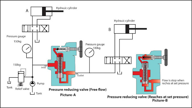
Pressure reducing valve circuit-1: In the diagram above a pressure reducing valve is used.
System maximum pressure is 150kg due to pressure relief valve is set to 150kg.
Now we have two cylinders set in two different pressure that is 150 kg for
cylinder A and 100 kg for cylinder B. To reduce the pressure for cylinder B we
set a pressure reducing valve at 100kg by adjusting the screw. Firstly, free
flow passage inside the valve (In picture-A) and when the pressure reaches at
set pressure (In picture-B) then the pressure acting below the spool and
closed the flow from inlet to outlet. Thus, cylinder is controlled in 100kg by
the pressure reducing valve. If the pressure below 100kg then the spool opens
slightly and allow the flow to reach 100kg pressure. For the cylinder A will
operate at 150kg directly at set pressure from relief valve.

|
|
Fig circuit-2: Pressure reducing valve |
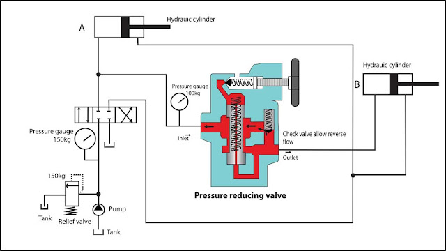
Pressure reducing valve circuit-2:
In this diagram has used one pieces
directional control valve and check valve operated pressure
reducing valve. Cylinder A will be acting with 150kg pressure that is set with
pressure relief valve. And cylinder B is connected through the pressure
reducing valve. Pressure will go from inlet to outlet and when pressure
reached at set pressure then pressure will be acting below the spool resulting
it closes the flow and cylinder will be operate at 100 kg. When the cylinder B
will go revers then the check valve will allow the reverse flow to the tank.
types of Pressure control valves
Also read:
Hydraulic directional control valve for hydraulic system

|
|
Fig: Flow control valve |
C) Flow control valve
Flow control valves are most commonly used in hydraulic system to regulates flow or pressure of hydraulic fluid. It maintain the controlled flow or pressure for the system. Flow control valve is developed according to their application of uses.types of Pressure control valves
Also read:
Hydraulic directional control valve for hydraulic system


Post a Comment